 |
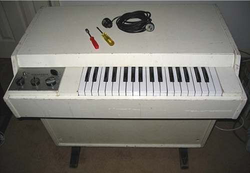
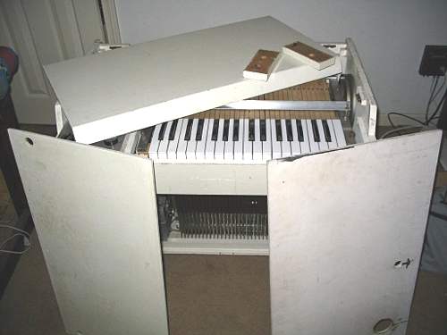
After you pull the power cord from the power supply, all the removable
panels are removed. This includes the top, the two cheek blocks
(usually located on either side of the keyboard), and the front and back
panels. |
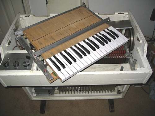 |
The keyboard is detached using four thumbscrews, one at each corner.
Underneath the keyboard is the tape take up box cover, which is a piece of
aluminum with a rolled edge (it is sitting on the flywheel for the picture). |
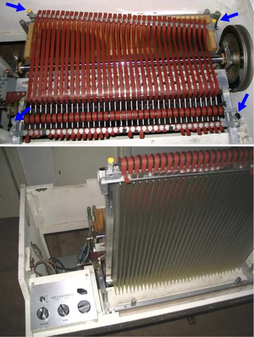 |
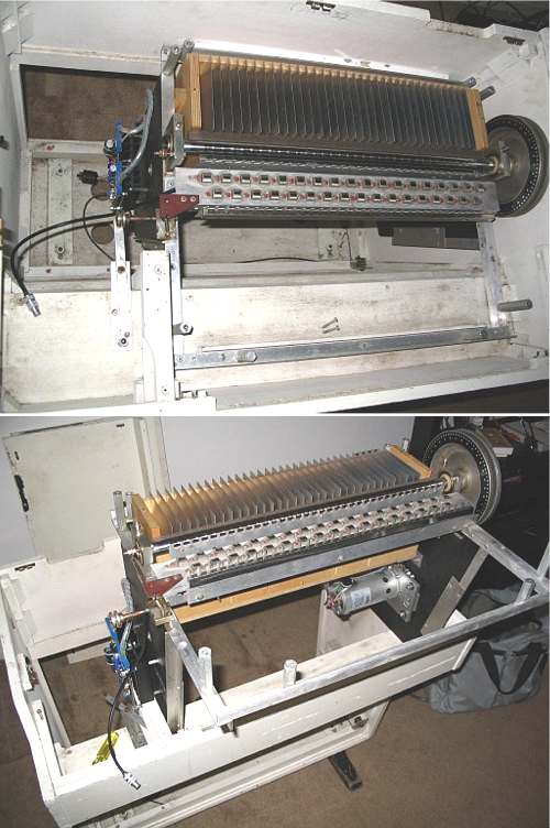
Now visible, the tapes can be removed by the four thumbscrews indicated
by the blue arrows. First you loosen the yellow thumbscrews which are
on a rod that is drawn back into the tape frame by the tapes as they are
pulled by the tape frame springs. Next the black thumbscrews loosen
the main part of the tape frame and allow the frame to be removed. |
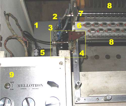 |
A look down into the Mellotron M400 with the keyboard and tape frame
removed.
- Power supply
- Motor controller (in this case the SMS-2)
- The coily wire is a ground going from the preamp box (under #9) to the
Mellotron's main frame
- Track selection mechanism
- Tape head block cable into the preamp
- Tape head block
- Pillow block and capstan
- Tape path
- Control panel (underneath is the preamp box)
|
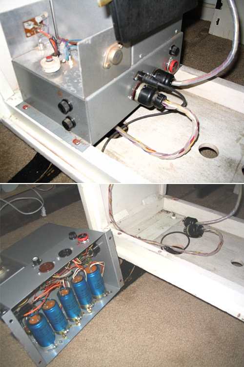 |
The power supply. One power cable goes to the preamp, the other to
the motor controller. The smallest cable that goes into the power
supply is for the audio. You can see the large capacitors in the power
supply. Under the top of the power supply is a large transformer. |
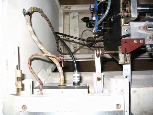 |
Another view down into the Mellotron, now with the power supply removed. |
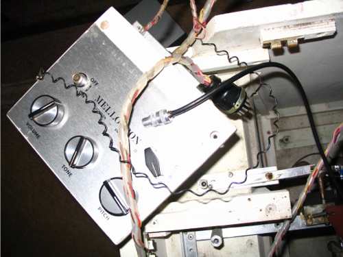 |
The control panel is held in by two screws. |
 |
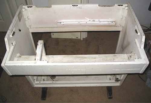
After the control panel is gone, the frame is left in there all by
itself...but not for long. |
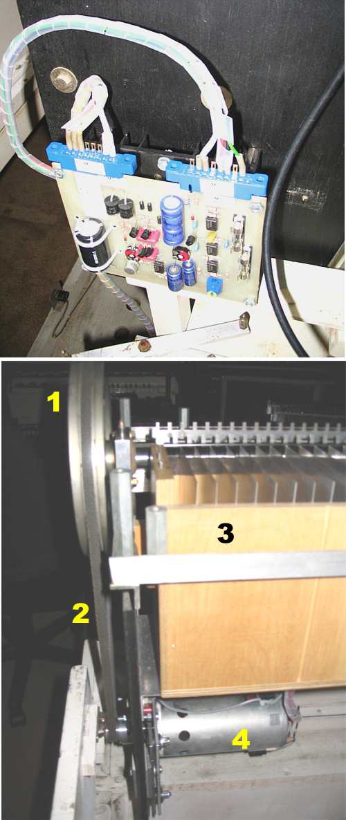 |
The main frame of the machine contains the tape path (guides, capstan,
take up box), motor, and motor controller. Top: The SMS-2 motor
controller.
Bottom:
- Flywheel
- Belt
- Tape take up box
- Motor
|
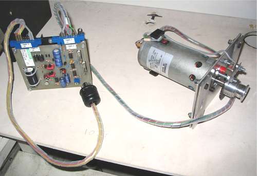 |
SMS-2 motor controller and brand new motor, both from
Streetly Electronics. |
Done.
With #1037 all packed in the car (well, without the woody bits), Jerry Korb and
I drove to just outside of Philadelphia to meet up with Jimmy, Nancy, and family
for some cheese steaks and suds. We spent some time in the basement
working out some tunes for the workshop. And we toured the area a bit,
visiting the historic Brandywine area, courtesy of Jimmy's fine hospitality!
First things first: Some prep work for the
workshop...-->